This article was translated from Hungarian to English by a_petri. It is mirrored here so that the information does not fall off the web. I, Jope, am not the author/designer.
I (a_petri) have only read this information in an old Hungarian Amiga magazine, and tried it myself. It seemed to be correct, and its result worked for me. However, I cannot guarantee that it would also work for anybody else, and hereby I present it on an "as is" basis, without warranty of any kind, so if you damage yourself, your disk drive, your Amiga, or anything/anybody else, it is not my liability.
First, you have to find an *appropriate* Chinon FZ-357 drive. Alas, only a part of the whole production was equipped with the same motor controller chip as the FB-357A model (the A3000/A4000 HD floppy drive); many of the FZ-357s were intended to be PC only, and therefore this hack won't work with them.
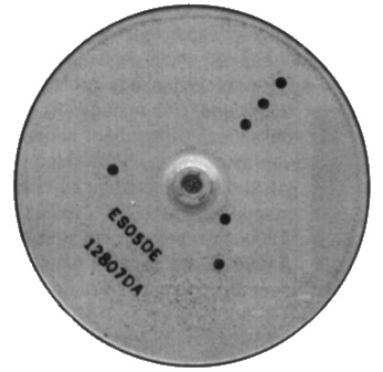
So you have to check the product sticker on the backside. If it says "MADE IN JAPAN", it is surely the PC-only variety. If it says "MADE IN MALAYSIA", you can continue with examining the flywheel (the big round exposed thing on the bottom of the drive). If it looks like this:
then you are lucky. The important thing is that the flywheel should have two *straight* lines of text, and not three arcs around a circle. If your FZ-357 matches with all these criteria, you can go on. If not, don't bother with it!
Remove the upper half of the metal lid first. It is held together with the lower half by four small clamps; you can pop them out with a screwdriver in the four semicircle-shaped holes at the sides of the drive.
Then remove the spring that pushes the disk holder mechanism down. This spring can be warped easily, so handle it with care.
Then the disk holder mechanism itself can be removed. It is held together by four small plastic thingies; remember their position, as they must be assembled later in the same way!
Finally you can unscrew the two screws at the bottom half of the metal lid and remove the remaining insides of the drive.
Turn over the insides, so that the original front panel of the drive looks away from you and the original bottom of the drive is upwards.
You can see two pieces of PCB: the 'upper' one, nearer to you, holds the 34-pin floppy cable connector and many other things, the 'lower' one holds the flywheel, the spinner motor and the motor controller chip. The 'upper' PCB is in the way now, so unscrew the two little screws that hold it and pull it slightly upwards and toward yourself, so the whole 'lower' PCB is exposed.
Be *VERY* careful, as this 'upper' PCB has three extremely thin foil cables (from the disk R/W heads and the head stepper motor) connected to it! If you damage these foil cables, the whole drive becomes useless!!!
I recommend to disconnect the foil cables from their sockets - with a very-very gentle hand! - and then to move the 'upper' PCB. The 'upper' and the 'lower' PCB is also connected with a piece of ribbon cable - it is much sturdier, but don't damage it either.
The controller chip is an SMD IC mounted diagonally at the lower right corner of the 'lower' PCB. Originally it should look approximately like this:
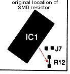
There are four solder pads beside it, forming a 'Y' shape, marked as J7.
The actual target of this step is that tiny SMD resistor, marked as R12, which is soldered between the central and the lower solder pads.
This SMD resistor must be removed from its current place and re-soldered between the central and upper left solder pads, as shown in this figure:
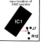
This operation requires some dexterity, and the use of an appropriate soldering iron (a low-power one - max. 30W - with a very pointy tip).
After successfully completing Step 3, you can put the 'upper' PCB back to its place (reconnect the foil cables if they were removed). There are some more modifications necessary on this PCB as well:
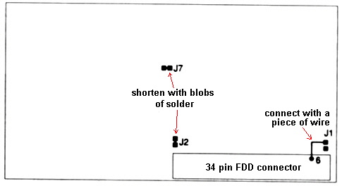
First drop two blobs of solder to the pairs of solder pads marked as J2 and J7, so they are shortened.
Then solder a short piece of insulated wire between one pad of J1 and pin #6 of the FDD connector header (it is the third pin from right in the upper row), as shown in the figure above.
The floppy drive can now be put together, basically by reversing the process described in Step 2.
The jumpering must also be modified, according to the following scheme:
         RDY
O O O O O O O
      |   | |
O O-O O O O O
  DS0 MM   TTL
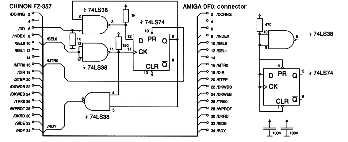
Unfortunately, all the hard work you've done is still not enough. A small external electronic circuit must also be built so that the Amiga motherboard could actually recognize the drive as a HD floppy unit.
The actual schematics of this circuit depend on whether you want an internal or an external floppy drive. The original article described a version for internal drives; it is shown here, without any comments.
Further versions, and a very detailed theory of operation, can be obtained from the archive "PCFloppy2Amiga.lha" in the hard/hack section of Aminet.